
inquiry
Leave Your Message

What Is an Inductance Sensor and How Does It Work?

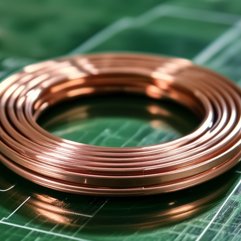
An Inductance Sensor converts changes in electromagnetic fields into measurable electrical signals. A copper coil sits beneath the sensing face. When a metal target approaches, eddy currents alter the coil’s inductance, amplitude, or oscillation frequency. The electronics detect that change and produce a switching signal, distance value, or position reading.

The principle sounds simple. The engineering is not. Target material, thickness, temperature, coil geometry, and mounting distance can all affect accuracy. A steel gear may produce a stronger response than aluminum. A warm machine may shift the signal slightly. Good designs compensate for these conditions through calibration and signal processing.

Market evidence shows why this technology remains important. The 2024 MarketsandMarkets Industrial Sensors report identifies factory automation, process control, and condition monitoring as major growth areas. Grand View Research also connects industrial sensor demand with predictive maintenance and connected manufacturing. These reports often group inductive devices within broader sensor categories, so their figures should not be treated as exact Inductance Sensor revenue.

Dr. Peter Ripka, a recognized magnetic-sensor researcher and author of Magnetic Sensors and Magnetometers, wrote, “Magnetic sensors are used in almost all areas of modern technology.” His observation fits inductive sensing, especially around motors, conveyors, machine tools, and safety systems.

Still, one limitation deserves attention. An Inductance Sensor does not “see” every material equally. It responds to electromagnetic behavior. That distinction is easy to overlook. This guide explains the working principle, main components, performance limits, and practical selection factors without hiding those trade-offs.
What Is an Inductance Sensor and How Does It Work?

Definition and Core Purpose of an Inductance Sensor

An inductance sensor is an electrical transducer that detects changes in a magnetic field. Its core purpose is simple: convert movement, position, distance, or metal presence into a measurable electrical signal. A typical device uses a copper coil, an oscillator, and signal-processing circuitry. The coil’s inductance depends on its turns, magnetic permeability, area, and length. When a metal target enters the electromagnetic field, it changes the coil’s impedance. The circuit then interprets that change as a controlled output. No physical contact is required.

This function supports reliable monitoring in automated equipment. The International Federation of Robotics reported 4.28 million industrial robots operating worldwide in 2023. Each robotic system may require multiple position or end-stop sensors. That figure does not measure inductance sensors directly. It does show the scale of environments needing compact feedback devices.

The Inductive Proximity Sensors Market forecast for 2023–2028 estimates growth from approximately USD 1.6 billion to USD 2.4 billion, with an annual growth rate near 8.5%.

In practice, engineers must calibrate the sensor for its target material and installation distance. Temperature, cable length, vibration, and electromagnetic noise can alter readings. A steel screw and an aluminum part may produce different response distances. The sensor may detect presence, but not always identify the object. That distinction is easy to miss. Field testing remains necessary, especially when a small air gap controls a large machine movement.


Key Components and Operating Principles

What Is an Inductance Sensor and How Does It Work?

Key Components and Operating Principles

An inductance sensor detects changes in a magnetic field caused by movement, distance, or a nearby conductive target. Its main components include a wound coil, a magnetic core, an oscillator, a signal-conditioning circuit, and an output stage. The coil is the sensing element. It listens.

When alternating current passes through the coil, it creates a changing magnetic field. A metal target entering this field alters the coil’s inductance, resistance, or energy loss. In a position sensor, a moving ferromagnetic core can also change the magnetic path. The oscillator detects this electrical change, while the signal-conditioning circuit converts it into a stable voltage, current, or switching signal. A controller then interprets that signal as position, presence, or displacement.

The operating principle is closely related to electromagnetic induction and magnetic reluctance. Greater target distance usually produces a weaker response, but the relationship is not always perfectly linear. Technicians often calibrate sensors against known gaps using a micrometer and a reference target. Temperature, mounting metal, vibration, cable length, and target material can affect the reading. Stainless steel, for example, may produce a different response from mild steel. That detail is easy to overlook.

A practical installation should leave enough space around the coil and secure the sensor firmly. Loose mounting can look like electrical noise. Shielding helps, but it does not fix poor alignment. The boundary is not always clean. -2

How Inductance Changes During Object Detection

An inductance sensor detects nearby conductive objects through changes in a magnetic field. Its sensing coil creates that field when alternating current flows through it. When a metal target enters the coil’s range, eddy currents form inside the target. These currents oppose the original field and change the coil’s effective inductance.

The relationship is practical: L depends on coil turns, magnetic permeability, area, and length. A nearby steel part usually reduces the measured inductance and shifts the oscillator frequency. The circuit then converts that shift into a switching signal or distance value. Target material matters. Steel, aluminum, and copper create different responses, even at identical distances. A real production test should measure each material separately.

Scale is also important. A 2024 MarketsandMarkets report estimated the global inductive proximity sensor market at about USD 1.5 billion in 2023, with continued growth expected through 2028. This demand reflects reliable detection in automated equipment. However, market growth does not guarantee perfect measurements. Temperature, coil geometry, mounting metal, and electrical noise can distort results. A 2023 industry analysis from Fortune Business Insights also linked sensor growth to factory automation and process monitoring. The numbers support adoption, but they do not replace calibration. Sometimes the simplest metal bracket causes the largest error.

Signal Processing and Measurement Steps

An inductance sensor detects changes in a magnetic field near its coil. A metal target changes the coil’s inductance, impedance, or resonant behavior. The sensor converts this physical change into an electrical signal. In practice, the target may be a rotating tooth, moving shaft, or flat metal surface.

Signal processing begins with stable AC excitation. The circuit drives the coil at a selected frequency and records its response. A small change can hide inside noise, especially near motors or switching power supplies. The sensing circuit then amplifies the signal without saturating the input stage. Demodulation separates the useful amplitude or phase change from the carrier frequency. A low-pass filter removes fast noise, but excessive filtering can delay the measurement. That trade-off is easy to underestimate.

The conditioned signal enters an analog-to-digital converter. Sampling must be fast enough for the expected measurement bandwidth. The software applies calibration data, including offset, sensitivity, and temperature correction. It then compares the result with a reference position or distance. During testing, I measure an empty target area before installing the moving part. This baseline reveals unwanted drift. I also check several target distances, not just one convenient point. Real systems are rarely perfect. Cable movement, coil temperature, and mounting gaps may still create errors. A second verification with a known mechanical gauge can expose mistakes that signal analysis alone misses.

Common Types, Uses, Advantages, and Limitations

An inductance sensor measures changes in an electromagnetic field. A coil creates that field when alternating current passes through it. Nearby metal changes the coil’s inductance, impedance, or magnetic coupling. The sensor then converts this change into a distance, position, speed, or presence signal.

Common types include variable-reluctance sensors, eddy-current sensors, and linear differential transformers. Variable-reluctance designs suit rotating targets, such as toothed wheels. Eddy-current models detect metal without physical contact and work well in machines with moving shafts.

Linear differential transformers measure precise movement, often in testing equipment and automated production lines. Typical uses include position feedback, vibration monitoring, speed measurement, thickness inspection, and proximity detection.

Their advantages are clear: no mechanical contact, strong durability, fast response, and good performance in oily or dusty areas. Yet they are not perfect. Nonmetallic targets may be invisible, temperature can shift readings, and nearby metal structures may create errors. Installation distance matters greatly.

Tips: Match the sensor type to the target material and motion. Keep the sensing face aligned. Check temperature limits before installation. Shield cables from strong electrical noise. A practical trial is valuable because catalog accuracy may not reflect your mounting conditions. I have found that small brackets can distort readings more than expected. That detail is easy to miss. Calibrate the complete assembly, not only the sensor.